Research on the Application of Breakthrough Curve Analyzers in Liquid Adsorbents for CO2 Capture

Download PDF

1. Introduction

Reducing atmospheric CO₂ concentrations remains one of the most pressing challenges in climate science and industrial decarbonization. Carbon Capture and Storage (CCS) has emerged as one of the most effective approaches for mitigating CO₂ emissions, with several core technologies under active development: membrane separation, solid adsorption, and liquid absorption.

Membrane separation relies on the selective permeation of gas molecules through materials such as inorganic or organic polymer membranes. Inorganic membranes (e.g., molecular sieves, porous ceramics) offer excellent chemical and thermal stability, but tend to have higher material and processing costs. Organic polymer membranes, while more economical, are limited by thermal

sensitivity, which restricts their use in high-temperature CO₂ capture scenarios.

Solid adsorption captures CO₂ through interactions between gas molecules and the surface of porous materials. Two mechanisms are possible:

  • Physical adsorption, driven by van der Waals forces, typically results in lower heat of adsorption and capacity but offers easier regeneration. Common adsorbents include activated carbon, zeolites, mesoporous silica, and metal-organic frameworks (MOFs).
  • Chemical adsorption involves stronger interactions through electron transfer or bonding at basic surface sites, offering higher selectivity and greater adsorption heat. Materials such as lithium salts, metal oxides, and chemically modified porous solids are frequently used.

Liquid absorption can also be divided into physical and chemical categories.

  • Physical solvents like Selexol (polyethylene glycol dimethyl ether) and Rectisol (methanol) dissolve CO₂ without chemical reaction, providing good performance at low temperatures with relatively low energy consumption.
  • Chemical solvents, typically alkaline solutions such as ammonia, NaOH, KOH, or amine-based compounds, react with CO₂ to form carbonates, bicarbonates, or carbamates. These reactions are reversible under specific conditions, enabling CO₂ capture and release.

While chemical solvents offer high capacity and fast absorption rates, several legacy solutions (e.g., KOH and ammonia) face challenges related to equipment corrosion, volatility, and handling safety. Today, amine-based absorbents are the most widely used due to their favorable balance of reactivity, efficiency, and scalability in industrial CO₂ capture.

2. Reaction Mechanism

Organic amines, commonly used in chemical CO₂ absorption systems, contain hydroxyl (–OH) and amino (–NH₂, –NHR, –NR₂) functional groups. The hydroxyl group improves water solubility, while the amino group increases the solution’s pH, enhancing alkalinity and CO₂ absorption potential.

The fundamental mechanism is an acid-base neutralization reaction, in which the weakly acidic CO₂ reacts with basic amines to form a water-soluble salt. This reaction is temperature-dependent and reversible:

  • CO₂ absorption occurs at lower temperatures (30–60 °C)
  • Desorption (release of CO₂) occurs at higher temperatures (90–120 °C)

Amine Classification and Reactivity

Organic amines are classified by the number of hydrogen atoms substituted on the nitrogen:

  • Primary amines (–NH₂): e.g., monoethanolamine (MEA)
  • Secondary amines (–NHR): e.g., diethanolamine (DEA), diisopropanolamine (DIPA)
  • Tertiary amines (–NR₂): e.g., N-methyldiethanolamine (MDEA)

The binding strength of CO₂ with these amines generally follows the order:

Primary > Secondary > Tertiary

Primary and Secondary Amines: Carbamate Formation

The widely accepted zwitterion mechanism (Caplow, Danckwerts) describes a two-step reaction:

  1. Formation of Zwitterion Intermediate
    CO₂ + R₁R₂NH ⇌ R₁R₂NH⁺–COO⁻
  2. Deprotonation by a Base (B)
    R₁R₂NH⁺–COO⁻ + B ⇌ BH⁺ + R₁R₂NCOO⁻

Here, the zwitterion reacts with a base (e.g., amine, OH⁻, or H₂O) to form a carbamate. The strong C–N bond in the carbamate makes the product highly stable, but also leads to:

  • Reduced CO₂ loading capacity
  • Higher regeneration energy requirements
  • Slower desorption rates

Maximum loading for primary/secondary amines is typically 0.5 mol CO₂ per 1 mol amine.

Tertiary Amines: Bicarbonate Formation

Unlike primary and secondary amines, tertiary amines lack reactive hydrogen atoms and do not form carbamates. Instead, they enhance CO₂ hydration and facilitate bicarbonate formation:

  1. CO₂ + H₂O ⇌ H⁺ + HCO₃⁻
  2. H⁺ + R₁R₂R₃N ⇌ R₁R₂R₃NH⁺

This route results in:

  • Slower absorption rates
  • Lower capacity

2.1 Mass Transfer Mechanism of CO₂ Absorption

The mass transfer process involved in CO₂ absorption is commonly described using the two-film theory, first proposed by Whitman and Lewis. This model divides the gas–liquid interface into five distinct regions (see Figure 1):

The mass transfer process involved in CO₂ absorption is commonly described using the two-film theory, first proposed by Whitman and Lewis. This model divides the gas–liquid interface into five distinct regions (see Figure 1):

  1. Bulk gas phase
  2. Gas film (a stagnant boundary layer near the gas side)
  3. Gas–liquid interface
  4. Liquid film (a stagnant boundary layer near the liquid side)
  5. Bulk liquid phase

In the bulk gas and liquid phases, turbulence is typically high, ensuring uniform composition. However, as the gas and liquid phases approach the interface, they pass through their respective stagnant film layers, where molecular diffusion becomes the dominant transport mechanism.

The CO₂ absorption sequence follows these steps:

  • CO₂ diffuses from the bulk gas phase to the gas film surface
  • It then moves across the gas film by molecular diffusion
  • At the gas–liquid interface, CO₂ dissolves into the liquid
  • The dissolved CO₂ diffuses through the liquid film
  • Finally, it enters the bulk liquid phase, where the chemical reaction with the solvent (e.g., amine) occurs

While the two-film theory is widely used and provides a useful conceptual framework, it does have limitations. In systems with free interfaces or high turbulence, the interface becomes unstable and continuously disrupted. Under these conditions, the assumption of two steady, well-defined stagnant films on either side of the interface becomes less accurate. In such cases, convective mixing and interfacial renewal models may offer better descriptions of the actual transport dynamics.

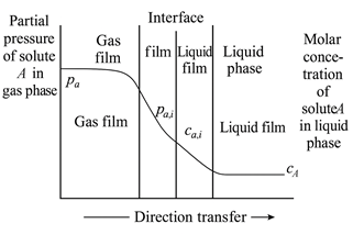
Figure 1 Schematic Diagram of the Two-Film Theory

2.2 Performance and Limitations of MEA-Based CO₂ Absorption

Monoethanolamine (MEA) is one of the most widely used absorbents for CO₂ capture. As a primary amine, MEA exhibits strong basicity and a low molecular weight, resulting in:

  • High reactivity
  • Rapid absorption kinetics
  • High CO₂ capacity per unit mass
  • Relatively low solvent cost

Due to these advantages, MEA-based absorption systems are commercially established and extensively deployed in both industrial and pilot-scale applications.

However, MEA is not without drawbacks. It has a high heat of reaction with CO₂, which translates to greater energy consumption during regeneration. MEA also tends to form stable amine carbonates and is prone to degradation when exposed to CO, sulfur compounds, or oxygen-containing gases, contributing to solvent loss and reduced operational efficiency.

Studies have shown that increasing MEA concentration improves CO₂ removal efficiency:

  • At 18 wt%, CO₂ removal is ~91%
  • At 30 wt%, it reaches ~96%
  • At 54 wt%, removal can exceed 98%

The improved performance is attributed to both increased vapor pressure and reaction enthalpy, which raise the temperature of the absorption solution. However, higher concentrations come with trade-offs:

  • Greater vaporization losses
  • Higher corrosion risk
  • Increased thermal degradation

For these reasons, MEA is most commonly used at ~30 wt% concentration, where performance and system stability are reasonably balanced. At higher concentrations, corrosion inhibitors are typically required.

Current research efforts are focused on:

  • Enhancing thermal and oxidative stability
  • Reducing energy consumption during regeneration
  • Developing modified or blended amine formulations to optimize performance and minimize drawbacks

2.3 Enhancing CO₂ Capture with Mixed Amine Solutions

To further improve CO₂ absorption efficiency and reduce energy consumption, blended alkanolamine solutions have become a key focus in solvent development. This strategy combines amines with high absorption capacity but slower kinetics with those offering faster reaction rates but lower capacity, aiming to strike an optimal balance between performance and regeneration efficiency.

By carefully selecting and mixing complementary amines, it is possible to enhance both the absorption and desorption characteristics of the solvent system. One promising approach involves blending monoethanolamine (MEA) with piperazine (PZ).

Research by Zhang Yaping [10] demonstrated that adding PZ to MEA significantly improves overall performance:

  • Absorption capacity increases with higher PZ content
  • Regeneration energy requirements decrease due to enhanced desorption kinetics

At a total amine concentration of 2 mol/L, the MEA–PZ blend achieved a saturated CO₂ absorption capacity of 206.1 mL/L, with a desorption efficiency of 86.38%. These findings highlight the potential of mixed amine systems to outperform single-component solvents in industrial carbon capture applications.

To further optimize CO₂ capture performance, recent research has focused on composite alkanolamine systems—blends that combine the strengths of individual amines to improve overall absorption capacity, regeneration efficiency, and cycling performance. These mixed-solvent systems aim to balance fast kinetics, high capacity, and low energy consumption.

Key Findings from Recent Studies

  • MEA–MDEA–PZ Blends
    Zhang et al. [11] evaluated the energy efficiency of a mixed amine system consisting of MEA, MDEA, and PZ. Their results showed a 15.22% to 49.92% reduction in energy consumption for CO₂ capture compared to MEA alone.
  • MEA with Secondary and Tertiary Amines
    Zhang Yu et al. [12] compared the performance of MEA blended with DEA, TEA, and AMP under controlled conditions (99.5% CO₂, 40 °C water bath). Among the mixtures, MEA + AMP exhibited the best absorption performance, while MEA + TEA showed the weakest.
  • MEA + DETA Mixtures
    Wen Juan et al. [13] found that increasing temperature, pressure, and DETA concentration improved both the CO₂ absorption capacity and rate of the MEA + DETA system.
  • AMP, PZ, and MEA Blends
    NWAOHA et al. [14] observed that mixed systems containing AMP, PZ, and MEA demonstrated higher cycling capacity and initial desorption rates than MEA alone.
  • Amine + Activator Systems
    Zhang Xinjun et al. [15] tested six combinations of alkanolamines (MEA, DEA, TEA) and activators (PZ, N-methylpiperazine [N-MPP], and aminoethylpiperazine [AEP]). The best performance was achieved using MEA as the main absorbent and AEP as the activator.
  • AMP-Based Blends with MEA and AEP
    Xiao Kunru et al. [16] studied the impact of mixing AMP with MEA or AEP. Under conditions of 25 °C and 101 kPa:

    • A 5:5 AMP:MEA ratio yielded the best absorption results
    • A 7:3 AMP:AEP ratio showed faster desorption
    • While the AMP:MEA blend had a 2.558% higher absorption capacity and 1.587% faster absorption rate, its desorption rate was 18.52% lower than AMP:AEP

These studies demonstrate that composite amine systems can significantly improve CO₂ capture by combining complementary properties—such as fast kinetics, high loading capacity, and reduced regeneration energy. Mixed alkanolamine formulations represent a promising path forward in the design of next-generation absorbents for industrial-scale carbon capture.

In addition to modifying amine formulations through blending, recent research has explored the use of catalysts and nanoparticles to further enhance CO₂ absorption performance, improve regeneration efficiency, and reduce overall energy consumption.

Catalyst-Enhanced Amine Systems

Ali Saleh Bairq et al. [17] reported that incorporating SO₄²⁻/ZrO₂/SiO₂ into monoethanolamine (MEA) resulted in significant improvements:

  • 36.48% reduction in regeneration energy consumption
  • 35.1% increase in desorption rate

These results highlight the potential of heterogeneous acid-base catalysts to promote the reversibility of CO₂ absorption reactions in amine systems.

Nanoparticle-Modified Absorbents

Nanoparticles have also emerged as effective additives, enhancing mass transfer, absorption rate, and desorption efficiency. Li Wenya et al. [18] studied the impact of TiO₂ and graphene oxide (GO) nanoparticles on diethylaminoethanol (DEEA) and N-methyldiethanolamine (MDEA) systems.

Key results compared to MEA without nanoparticles include:

System Absorption Capacity Absorption Rate Desorption Capacity
30% DEEA + 0.05% 25 nm TiO₂
9.86% 33.43% 10.72%
30% MDEA + 0.05% 40 nm TiO₂ 11.26% 49.72% 9.19%
30% MDEA + 0.06% GO 13.8% 39.23% 26.66%

These nano-enhanced solvents demonstrated significant improvements in both absorption and regeneration metrics, offering a path to more efficient CO₂ capture processes.

Effect of Nanoparticle Size

Jiang et al. [19] compared the performance of 10 nm and 20 nm TiO₂ nanoparticles in MEA systems. While smaller particles offer higher surface activity, they are more prone to agglomeration, which can reduce effectiveness. In contrast, larger particles (20 nm) were found to more effectively disturb the mass transfer boundary layer, enhancing local mixing, concentration gradients, and overall mass transfer performance.

Incorporating catalysts or engineered nanoparticles into alkanolamine solutions is a promising direction for improving the kinetics, capacity, and energy efficiency of CO₂ capture systems. These additive-based approaches represent a valuable area of future research for next-generation absorbents.

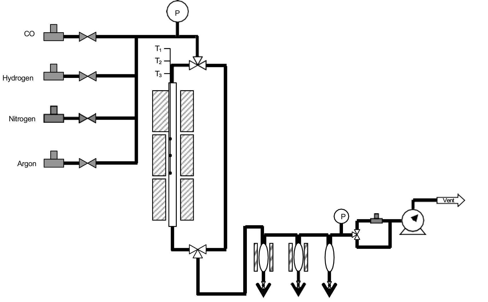
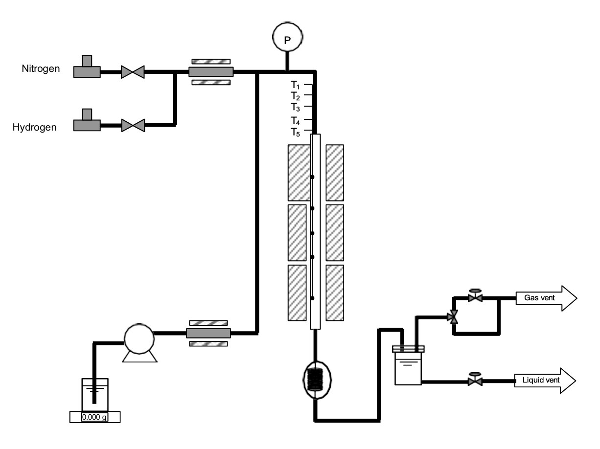
3.0 Experimental Method

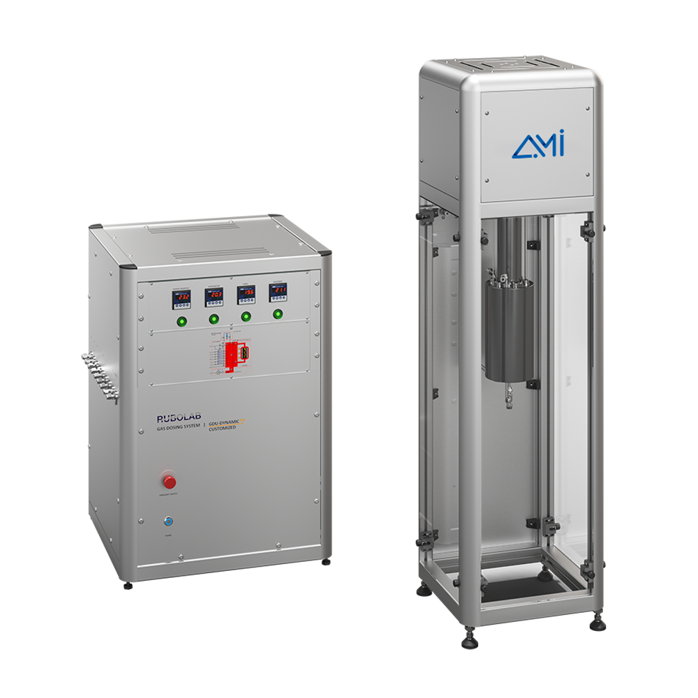
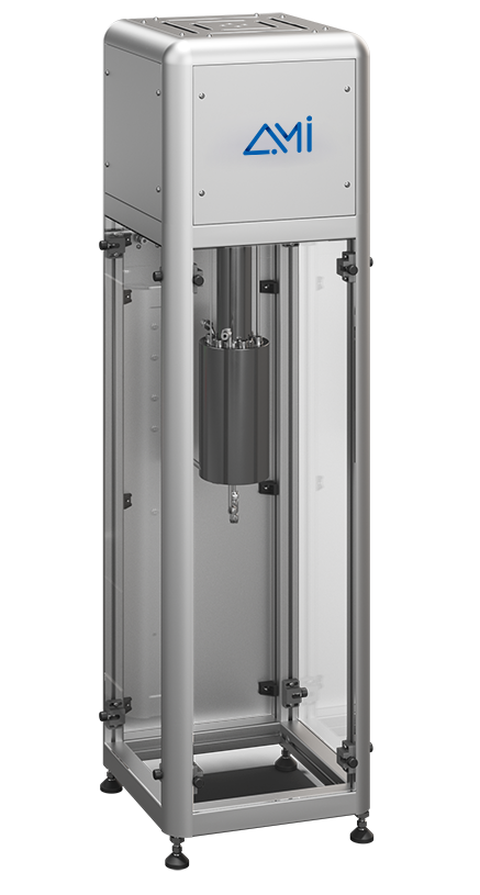
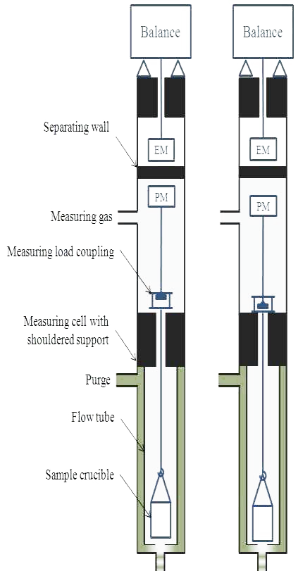
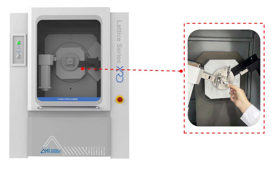
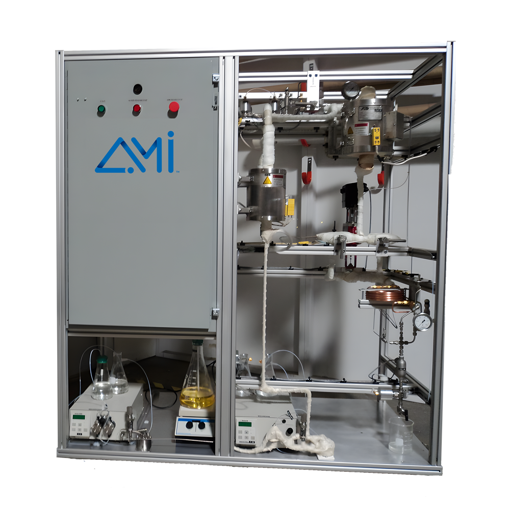
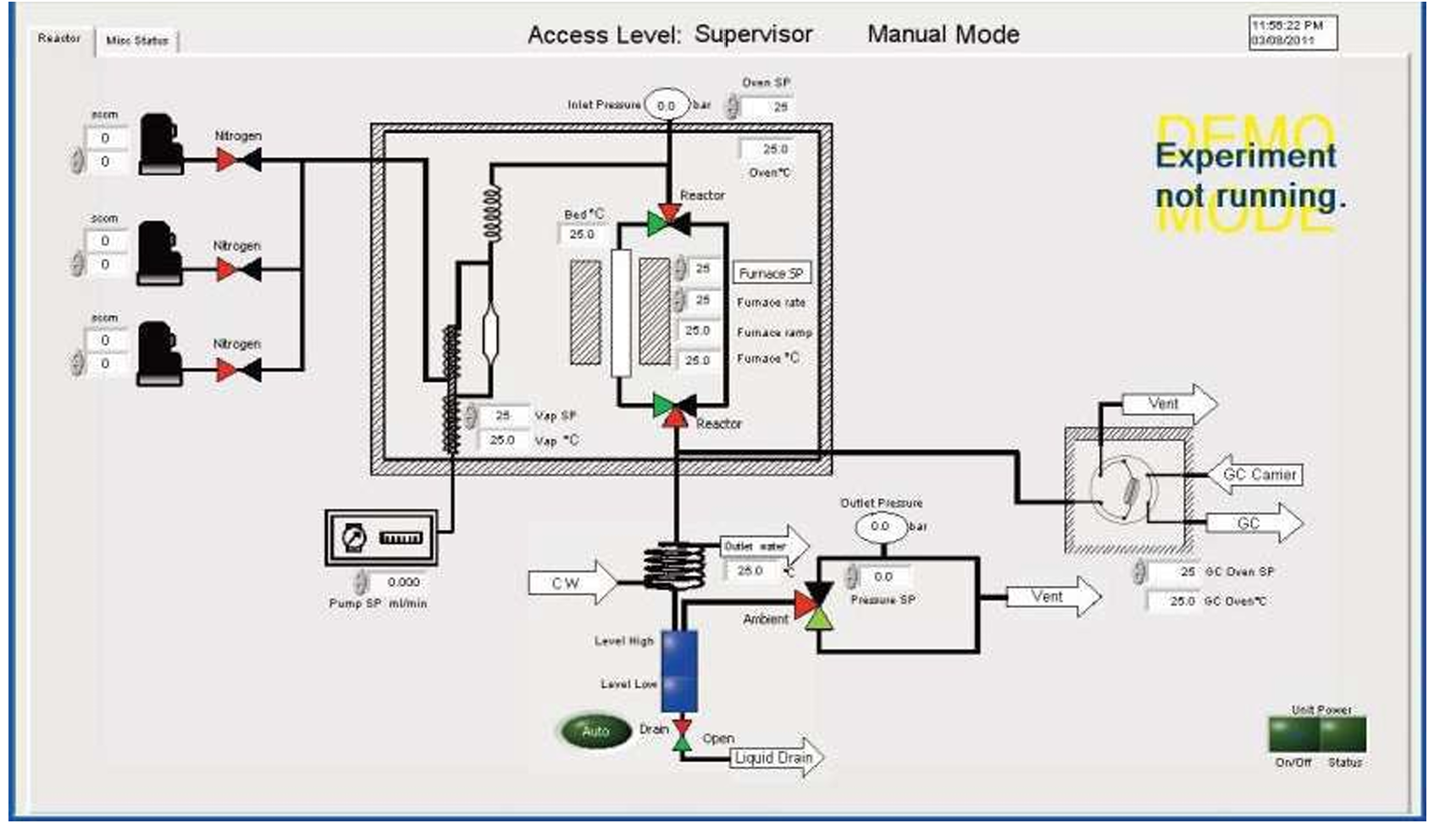
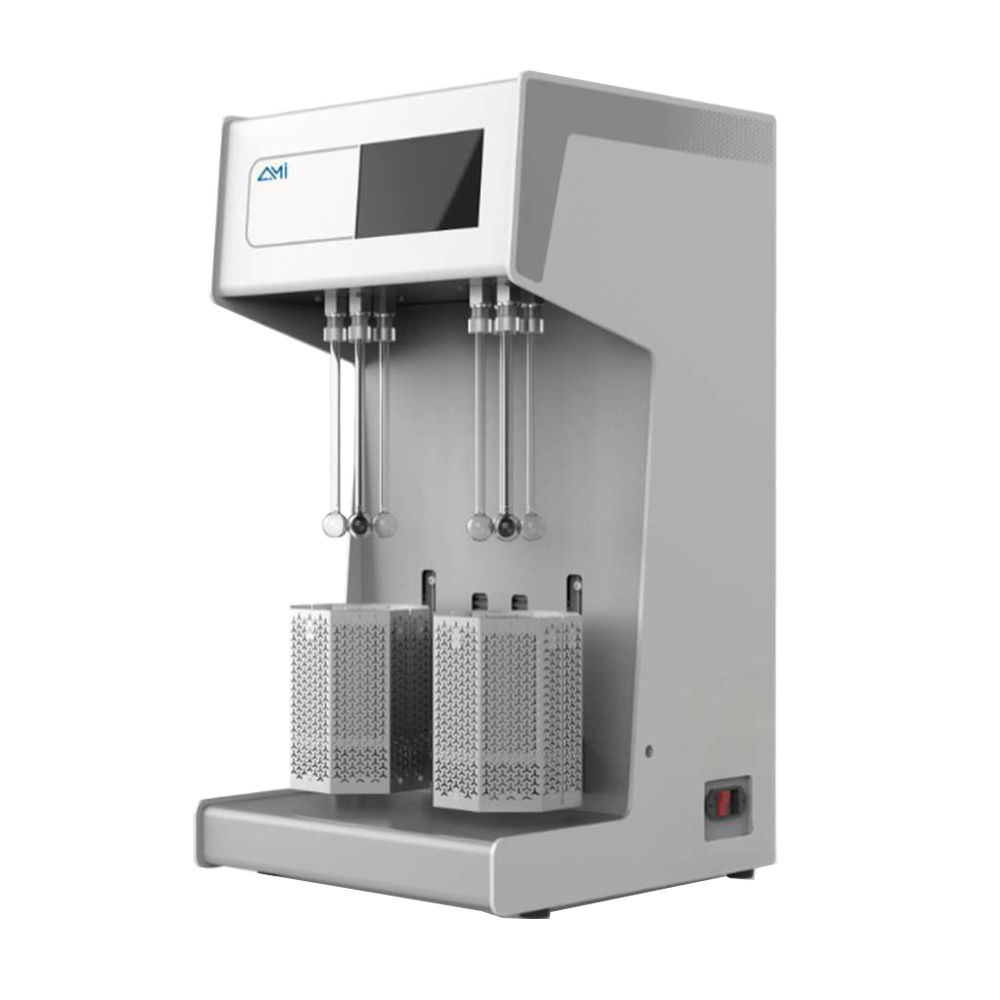
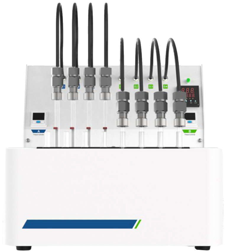
To study the CO₂ adsorption behavior of monoethanolamine (MEA), we conducted a series of experiments using the BTSorb 100 (formally MIX100) breakthrough curve and mass transfer analyzer on a commercially available MEA solution.

Test Procedure

  1. Sample Preparation:
    10 mL of MEA solution was measured for testing. Repeatability was verified through multiple runs.
  2. Gas Flow Setup:
    • Adsorbate gas: CO₂ at a flow rate of 15 mL/min
    • Carrier gas: N₂ at a flow rate of 185 mL/min
  3. Temperature Control:
    The test was performed at a constant temperature of 40 °C. To eliminate interference from MEA vapor during measurement:

    • A condenser was installed at the outlet of the sample cell and maintained at 0 °C
    • A desiccant was placed in the cold trap to remove residual moisture from the gas stream

Experimental Conditions - Details of the test setup are summarized in Table 1 below.

Table 1 Experimental Conditions for Ethanolamine


Sample Volume (ml) N₂ Flow Rate (ml/min) CO₂ Flow Rate (ml/min) Temperature (°C) Pressure (bar)
10-1 185 15 40 1
10-1 (Re-adsorption) 185 15 40 1
10-2 185 15 40 1


  • 10-1 (Re-adsorption):
    This test refers to a repeated CO₂ adsorption experiment performed after desorption. Regeneration was carried out by heating the sample cell to 120 °C. Once the CO₂ concentration at the outlet dropped below 0.5%, the adsorption process was repeated under the same conditions.
  • 10-2 (Re-sampling):
    Represents an additional test performed by sampling fresh MEA solution under the same test conditions to assess repeatability.
  • System Preparation:
    Prior to each experiment, the system was purged with nitrogen (N₂) at 185 mL/min to ensure complete removal of residual CO₂ from the setup.

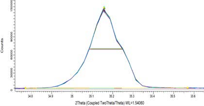
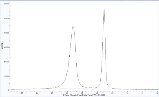
As shown in Figure 2, the breakthrough curves from the 10-1 and 10-2 tests are nearly identical, demonstrating excellent repeatability of the experimental setup. However, the 10-1 (re-adsorption) curve exhibits a slightly shorter breakthrough time, indicating a marginal decrease in adsorption capacity following the regeneration cycle.

This result suggests that while MEA retains good performance after regeneration, some loss of adsorption efficiency may occur, likely due to incomplete solvent recovery or minor thermal degradation during the desorption process.

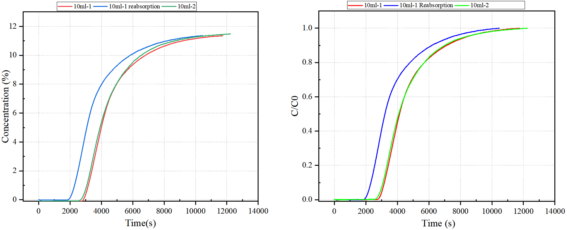
Figure 2 Breakthrough Curve of Ethanolamine MEA

Based on the calculated results presented in Table 2, the measured CO₂ adsorption capacities for the two 10 mL monoethanolamine (MEA) samples were 0.4875 mol/mol and 0.4822 mol/mol, respectively. These values are consistent with the commonly reported commercial MEA capacity of approximately 0.5 mol CO₂ per mol amine, validating the reliability of the test conditions and measurement approach.

Following desorption and re-adsorption (Test 10-1), the measured adsorption capacity decreased to 0.3875 mol/mol, indicating a notable decline in performance after regeneration. This reduction may be attributed to partial thermal degradation of MEA or incomplete recovery of active absorption sites during the desorption cycle.

Table 2 Calculated Adsorption Capacity Results for Ethanolamine MEA

Sample Name Adsorption Capacity mol(CO₂)/mol(MEA)
10ml-1 0.4875
10ml-1 (Re-adsorption 0.3875
10ml-2 0.4822

4.0 Conclusions

This study demonstrates the viability of using monoethanolamine (MEA) as a chemical absorbent for CO₂ capture under ambient conditions. Through a combination of theoretical review and experimental validation using the BTSorb 100 (formally MIX100) breakthrough analyzer, MEA was shown to achieve CO₂ adsorption capacities consistent with commercial expectations (~0.5 mol/mol). While regeneration was successful, a decline in adsorption performance after the desorption cycle suggests some loss in efficiency, likely due to thermal degradation or incomplete solvent recovery.

The data confirms that MEA remains a strong candidate for CO₂ absorption systems, especially when optimized with temperature control and proper regeneration protocols. Future improvements may be achieved through blending with secondary or tertiary amines, use of corrosion inhibitors, or incorporation of nanomaterials and catalysts to reduce energy consumption and enhance cycling performance. These directions represent promising opportunities for scaling liquid-phase CO₂ capture in industrial applications.

5.0 References

[1] Wang J., Huang L., Yang R., et al. Recent advances in solid sorbents for CO₂ capture and new development trends. Energy & Environmental Science, 2014, 7: 3478–3518.

[2] Venna S.R., Carreon M.A. Highly permeable zeolite imidazolate framework-8 membranes for CO₂/CH₄ separation. Journal of the American Chemical Society, 2010, 132(1): 76–78.

[3] Huang Yuhui. Research on the Degradation of Mixed Amine Absorbents for Flue Gas CO₂ Chemical Absorption Technology [D]. Hangzhou: Zhejiang University, 2021.

[4] Wang Dong, et al. Research progress on solid and liquid adsorbents for carbon dioxide capture.

STA 650 1000 1200 1500

INTRODUCTION

  • AMI is pleased to introduce its next-generation Simultaneous Thermal Analyzer (STA), a state-of-the-art instrument designed for advanced thermal analysis. Incorporating a 0.1-microgram balance resolution, sophisticated control algorithms, and an innovative hang-down design, this analyzer delivers exceptional precision and reliability in an affordable, high-performance system.
  • The STA Series enables simultaneous Thermogravimetric Analysis (TGA) and Differential Scanning Calorimetry (DSC)/Differential Thermal Analysis (DTA) on a single sample within a single run. Built for reliability and precision, the STA delivers comprehensive thermal profiles without the need to run multiple experiments—saving you both time and sample material.
  • Engineered for quality control, routine testing, academic research, and industrial R&D, the STA Series combines robust construction with user-friendly intuitive software, offering a cost-effective solution for high-precision thermal analysis.
  • The STA is controlled by the Infinity Pro Thermal Analysis software. This unique Windows based software offers a very simple interface with all the features you need to analyze your thermal data.
  • STA Simultaneous Thermal Analyzer

MATERIALS

  • ● Polymers
  • ● Chemicals
  • ● Petrochemicals
  • ● Polymorphs
  • ● Superconductors
  • ● Ceramics
  • ● Glasses
  • ● Composites
  • ● Metals
  • ● Engineered alloys
  • ● Pharmaceuticals
  • ● Catalyst Research
  • ● Building Materials
  • ● Propellants
  • ● Explosives
  • ● Electronic Components
  • ● Coals & other fuels
  • ● Catalysts
  • ● Nuclear Science Materials
  • ● Food and Biomaterials

FEATURES

  • True Hang-Down Balance Design
  • Industry-leading stability, sensitivity, and long-term drift resistance for reliable and repeatable measurements without the need for buoyancy corrective experiments.
  • High Sensitivity Microbalance
  • Sub-microgram-level accuracy across a broad temperature range, providing confidence in your thermal and mass loss data.
  • 24-Bit Resolution
  • High-precision measurement of temperature, delta T, and weight with minimal noise and high digital fidelity.
  • Small Swept Volume Furnace Cup (7.5mL)
  • Enhances temperature uniformity and gas exchange efficiency.
  • Simultaneous TGA/DSC or DTA
  • Perform thermogravimetric and calorimetric analyses in a single run— ideal for decomposition, oxidation, and phase transitions.
  • Dual Purge Gas System
  • Separate channels for purge and protective gases allow for fine control of the experimental atmosphere.
  • Broad Temperature Range
  • Furnace operation up to 1500°C under inert, oxidizing, or reducing gas environments.
  • Motor-Driven Furnace Lift
  • Ensures automated, smooth movement of the furnace for consistent sample positioning.

OPTIONS

  • Evolved Gas Analysis (EGA) Compatibility
  • Interface with mass spectrometry (MS) or FTIR systems for evolved gas studies during thermal decomposition.
  • 4-Gas Selector System
  • Automates delivery of up to four different gases for programmable switching during analysis.
  • Sub-Ambient System (650°C Model)
  • Low-temperature furnace models support experiments starting below room temperature
  • High-Temperature Flexibility
  • Optional DSC-only high-temperature mode to allow DSC-only to 1,500°C
    Optional TGA-only high-capacity mode for larger or reactive samples

EXAMPLES

  • Barium Chloride
  • This is an example of a reference material that shows temperature and enthalpy accuracy. In addition, this represents a good example of a fused peak analysis.
  • Calcium Oxalate
  • Calcium Oxalate is an excellent demonstration material for both DSC and TGA. This sample was run in the presence of Oxygen. The first DSC peak has an associated weight loss and represents bound water.
  • STA data analysis

SPECIFICATIONS

  • Temperature -40°C-650°C Ambient to 1200°C Ambient to 1500°C
    Programmed Rate 0.1-100 °C/min 0.1-40 °C/min
    DSC Sensitivity <1 μW <4 μW
    TGA Range 400 mg
    TGA Readability 0.1 μg
    Thermocouple Type K Type R
    DSC/DTA mode Yes

RuboSORP MSB

INTRODUCTION

  • Accurate mass measurement is critical across materials science, chemical engineering, energy storage, and catalysis research. While traditional electronic microbalances offer high precision under standard laboratory conditions, they are often unsuitable for extreme environments involving high pressure, high temperature, or corrosive and reactive gases. The Magnetic Suspension Balance (MSB) addresses these challenges with contactless, high-resolution mass measurement in fully isolated, controlled environments.
  • The RuboSORP MSB employs a magnetically coupled weighing system that physically separates the microbalance from the sample atmosphere. This design allows for real-time gravimetric analysis under demanding conditions—without the need for purge gases or proximity protections—enabling accurate study of sorption processes, adsorption kinetics, vapor-liquid equilibria, and gas-phase density.
  • Samples are housed within a sealed, corrosion-resistant chamber. Any change in mass is transmitted through a magnetic assembly to a high-precision microbalance operating at ambient pressure. This contact-free transfer ensures long-term stability, exceptional resolution, and minimal signal drift—even over extended experimental durations or during thermal cycling.
  • A standout feature of the RuboSORP MSB is its dual-sample capability. The system can simultaneously analyze two samples or substitute one with a calibrated sinker for direct gas density measurement via Archimedes’ principle. This is especially valuable in high-pressure or multi-component gas systems where conventional equations of state fall short.
  • RuboSORP MSB

FEATURES

  • Automatic Drift Correction & Recovery
  • The RuboSORP MSB actively compensates for pressure and temperature-induced drift, maintaining accurate readings throughout adsorption, desorption, or thermal cycles. A builtin self-recovery system prevents data loss in case of unexpected motion or imbalance, ensuring uninterrupted experiments.
  • Density / Double Sample Measurement
  • The dual sample measurement module enables experiments with two samples simultaneously. One position can be fitted with an inert float or calibrated sinker, allowing direct measurement of gas density via Archimedes' principle—especially critical at high temperatures and pressures where traditional equation-of-state methods become unreliable. This capability is particularly valuable in multicomponent gas adsorption studies, as it enables real-time tracking of composition changes without the need for external gas analysis tools such as chromatography.
  • Optional Viewing Cells
  • Optional high-pressure viewing cells provide in-situ visual access to the sample chamber, enabling direct observation of swelling behavior, phase transitions, and vapor–liquid equilibrium phenomena. A highstrength window allows monitoring of expansion and adsorption processes in polymer and ionic liquid samples through an integrated image acquisition system. The system operates reliably under extreme conditions, with a maximum temperature of 200 °C and pressure up to 35 MPa.
  • Optional Viewing Cell
  • Modular Design & Flexible Configuration
  • The RuboSORP MSB features a fully modular setup with interchangeable components for pressure, temperature, gas dosing, and reactor control. Visual cells, custom sample holders, and a range of heating options—from cryogenic to high-temperature—ensure adaptability to diverse applications.
  • Smart Software & Data Integrity
  • Automated control software manages all experimental parameters in real time and includes built-in uncertainty analysis. It supports ISO 9001 and GUM standards, generates adsorption curves on the fly, and logs data in accessible formats for seamless analysis and reporting.
  • Sealed Coupling Chamber
  • Enables safe use of toxic, reactive, and corrosive fluids—allowing experiments to be conducted under real-world conditions without compromising balance integrity.
  • Customizable Sample Cells and Reaction Baskets
  • To simulate real-world reaction conditions, AMI offers a range of interchangeable measuring cells and sample basket modules. Sample cell dimensions—up to 70 mm in diameter—can be customized to suit various materials and experimental needs. AMI also provides tailored solutions, including the development of new basket designs based on customer requirements. Available options include FF-type fixed bed baskets, FT-type high-efficiency reaction baskets, and specialized baskets designed for ionic liquids.
  • Industry-Leading Sample Capacity
  • Supports the widest max sample capacity, accommodating large or irregular samples without compromising accuracy—ideal for heterogeneous materials and custom applications.
  • Exceptional Stability Over Time
  • The system uses a load decoupling mechanism to periodically remove the sample from the balance, perform automatic recalibration, and resume the experiment—ensuring long-term measurement stability and eliminating drift during extended runs.

DATA ANALYSIS

  • The RuboSORP MSB can measure various types of gas adsorption isotherms, determine adsorption isobars, obtain adsorption kinetics curves, and conduct multi-component competitive adsorption.
  • It can handle all common gases, including but not limited to hydrogen, nitrogen, methane, carbon monoxide, carbon dioxide, and oxygen, as well as corrosive gases such as: chlorine, hydrogen sulfide, and sulfur dioxide. Additionally, it can be paired with a visual measurement module or a separate visual observation module to study the absorption or volume change of supercritical carbon dioxide.
  • Application of two-component competitive adsorption
  • For the study of competitive adsorption of two-component gases, AMI offers an ingenious solution, which is to measure the density of the gas mixture at adsorption equilibrium in real time through a special three-position Magnetic Suspension Balance, and then calculate the adsorption amount of each gas in the two component gas in real time through software, without the need for external chromatography/mass spectrometry tools.
  • Sulcis coal sample carbon dioxide/methane binary competitive adsorption data

PRESSURE SYSTEM

  • The RuboSORP MSB’s gas system is equipped with two high-precision pressure sensors: a sensor with a range to 5 MPa and a sensor with a range to 40 MPa, both with an accuracy of 0.01 bar
  • Gas System Models:
  • System Type Model No. Pressure range(bar) Temperature Control Intake quantity Option
    Dynamic Gas System GDU-150D-A 150 none 2 Mechanical pump/
    Molecular pump
    Vapor dosing
    Extra gas path
    Additional pressure sensor
    GDU-150D-H 150 100℃ 2
    GDU-350D-A 350 none 2
    GDU-350D-H 350 100℃ 2
    Static Gas System GDU-150S-A 150 none 2 Mechanical pump/
    Molecular pump
    Vapor dosing
    Extra gas path
    Additional pressure sensor
    GDU-150S-H 150 100℃ 2
    GDU-150S-H mix 150 100℃ 3
    GDU-350S-A 350 none 2
    GDU-350S-H 350 100℃ 2
    GDU-350S-H mix 350 100℃ 3
    GDU-700S-A 700 none 2
    GDU-700S-H 700 100℃ 2
    GDU-700S-H mix 700 100℃ 3

SPECIFICATIONS

  • Model Max Pressure Max Temperature Max Sample Loading Resolution Vacuum Option GDU Capability View Cell & Camera Option Model
    MSB-150 150bar 400°C 25g 10μg Yes Dynamic or Static Yes MSB-150
    MSB-150 150bar 400°C 50g 10μg Yes Dynamic or Static Yes MSB-150
    MSB-150 150bar 400°C 10g 1μg Yes Dynamic or Static Yes MSB-150
    MSB-350 350bar 400°C 25g 10μg Yes Dynamic or Static Yes MSB-350
    MSB-350 350bar 400°C 50g 10μg Yes Dynamic or Static Yes MSB-350
    MSB-350 350bar 400°C 10g 1μg Yes Dynamic or Static Yes MSB-350
    MSB-700 700bar 150°C 25g 10μg Yes Static Only No MSB-700
    MSB-700 700bar 150°C 50g 10μg Yes Static Only No MSB-700
    MSB-700 700bar 150°C 10g 1μg Yes Static Only No MSB-700

APPLICATIONS

  • Hydrogen & Methane Storage
  • High-pressure isotherms provide real-world data critical for evaluating advanced storage materials including MOFs and metal hydrides.
  • Corrosive Gas Research
  • Quantify adsorption of SO2, HF, Cl2, and similar aggressive gases at controlled temperature and pressure—safely and accurately.
  • Supercritical CO2 Studies
  • Track sorption behavior and reaction kinetics in polymers, biomass, or coal under supercritical conditions with full visual feedback and gas-phase density measurement.
  • Multi-Component Adsorption
  • By integrating a calibrated gas mixer, the MSB measures real-time competitive adsorption of gas mixtures, eliminating the need for offline chromatography.

RuboSORP MSB DVS

INTRODUCTION

  • Designed for advanced materials research, this system combines a precisely controlled environment—with wide-ranging vapor delivery, temperature flexibility, and compatibility with aggressive chemical conditions—to enable complex DVS experiments across a variety of challenging applications. The MSB design integrates effortlessly with automated vapor and temperature regulation, user-defined testing protocols, advanced data analysis, and comprehensive reporting, enhancing both workflow efficiency and experimental clarity.
  • What truly distinguishes MSB-based systems from traditional dynamic vapor sorption instruments is their contactless measurement principle—ensuring a stable, contamination-free environment for collecting high-quality data under real-world conditions.
  • VAPOR SORPTION WITH:
  • √ High Precision
    √ Corrosive Environments
    √ Drift Zeroing
    √ High-throughput
    √ Wide Temperature Range
  • RuboSORP MSB DVS

KEY FEATURES

  • Magnetic Suspension Balance Technology:
  • High Sensitivity and Accuracy:
  • Measures weight changes with microgram precision. Magnetic suspension eliminates mechanical contact, reducing friction and wear.
  • Temperature Stability:
  • Operates reliably over wide temperature ranges (e.g., -20°C to 400°C).
  • Corrosion Resistance:
  • Ideal for working with reactive or corrosive vapors since the sample is isolated from the balance.
  • Advantages Over Conventional DVS Systems:
  • No Mechanical Wear:
  • Magnetic suspension eliminates the need for a conventional balance in contact with the sample.
  • Reduced Drift:
  • Long-term experiments benefit from high stability with drift correction at each data point. Versatile Environmental Control: Operates with a variety of gases and vapors under controlled conditions.
  • High-Throughput:
  • Runs two samples simultaneously.

BENEFITS

  • Over nearly four decades of refinement, magnetic suspension balances have become an essential tool across disciplines including materials science, pharmaceuticals, environmental engineering, food technology, and energy materials research. Their ability to accurately measure weight changes under varied and sometimes corrosive/harsh conditions has proven invaluable for investigating adsorption phenomena, elucidating kinetics, and determining fluid properties such as vapor pressure and density.
  • By employing MSB technology, the system isolates the sample from external mechanical influences, vibrations, and environmental fluctuations. This isolation results in an exceptionally stable baseline and highly sensitive mass resolution, capturing even the most subtle sorption events with reproducible precision. The hermetically sealed chamber design further ensures that sample integrity is maintained throughout the experiment, minimizing the risk of contamination and thereby yielding more reliable and representative sorption isotherms and kinetics data.
  • Conventional gravimetric analysis in dynamic vapor sorption (DVS) often relies on mechanical connections and traditional balances. These systems can introduce drift, frictional effects, and frequent re-calibration requirements, which may compromise measurement quality and long-term stability.
  • Comparison between conventional microbalances and magnetic suspension balance
  • In contrast, magnetic suspension balance technology offers a fundamentally different approach, enabling direct measurement of mass changes without mechanical contact to the sample crucible.

SCHEMATICS

  • Vapor 10D Diagram
  • Vapor 10S Diagram

SCHEMATICS

  • Mass Range Vapor-10S Vapor-1S Vapor-10D Vapor-1D
    Resolution 10 μg 1 μg 10 μg 1 μg
    Maximum Sample Loading 15 g 5 g 15 g 5 g
    Sample Throughput 2
    Pressure Range Up to 1 bar -isotherm measurement Ambient -dynamic gas flow
    Air Bath Temperature Control 150°C
    Temperature Range of Sample Pretreatment Up to 400°C
    Material of Sample Crucible Stainless steel or ceramic, or quartz
    Gas or Vapor Water vapor, organic vapor, CO2, corrosive gases
      Options
    Circulating Bath Thermostat -20°C-150°C
    Additional Pressure Sensor 10 torr/1 torr/0.1 torr/Customized scale
    Multi-gas ports Four gas inlet ports
    High Pressure Option 10 bar


Lattice Series

INTRODUCTION

  • The Lattice Series redefines benchtop X-ray diffraction by combining high-power performance with compact design. Equipped with a powerful 600 W (Lattice Mini) or 1600 W X-ray source and a high-efficiency, direct-read 2D photon detector, the Lattice Series delivers exceptional data intensity and accuracy—making it ideal for demanding analytical environments.
  • Available in three configurations—Lattice Mini, Lattice Basic, and Lattice Pro—this series accommodates a wide range of technical and budgetary needs, from simple phase identification to complex in-situ studies. All models offer excellent signal-to-noise ratio and fast scan speeds, providing lab-grade data from a desktop system.
  • Whether you're analyzing complex powders, crystalline materials, or conducting highthroughput measurements, the Lattice Series provides lab-grade results with speed, power, and precision—all in a desktop footprint.
  • Lattice Series Instrument

MODEL SERIES

  • The Lattice Mini is the ideal entry point for high-quality X-ray diffraction. Designed for users who need reliable phase identification and material characterization in a truly space-saving format, the Lattice Mini delivers powerful performance in a compact, affordable package.
  • Ideal for:
  • • University and teaching laboratories
    • Small research groups
    • Routine QA/QC in ceramics, metals, and minerals
    • Rapid phase screening and basic material studies
  • The Lattice Basic is designed for laboratories that require dependable, high-throughput diffraction without the complexity of advanced custom configurations. With high angular resolution and a direct-read 2D photon detector, the Lattice Basic delivers fast, accurate results across a wide range of powder samples. It’s an excellent choice for users who prioritize precision, speed, and reliability—at an efficient price point.
  • Ideal for:
  • • QA/QC labs
    • Materials characterization
    • Educational and institutional research
    • Cement, ceramics, metals, and pharmaceuticals
  • The Lattice Pro is built for the most demanding applications. Featuring Theta–Theta geometry for enhanced sample stability and accessory support, it enables precise, high-performance analysis for advanced materials, coatings, and stress testing.
  • Ideal for:
  • • Advanced R&D environments
    • Dynamic experiments
    • Residual stress analysis
    • Film, coating, and thin-layer characterization
    • Battery and energy materials research

KEY FEATURES

  • • High-Power X-ray Source
  • Choose between 600 W or 1600 W configurations for high-intensity data collection and rapid scanning.
  • • 2D Photon Direct-Read Detector
  • A 256 × 256 pixel array captures sharp, high-resolution diffraction patterns with an excellent signal-to-noise ratio.
  • • Exceptional Angular Accuracy
  • Achieve step sizes as small as ±0.01° 2θ and ensure a consistent peak matching with standard reference materials.
  • • Flexible Goniometer Options
  • Theta–2Theta geometry for standard analysis (Mini & Basic) or Theta–Theta for enhanced sample stability (Pro).
  • • Fast, Reliable Scanning
  • Obtain full-spectrum data in minutes—ideal for routine QA and high-throughput labs.
  • • Compact Benchtop Design
  • Fits seamlessly into modern lab environments without sacrificing performance or requiring floor space.
  • • Expandable Functionality (Lattice Pro)
  • Supports advanced modules for residual stress testing, high-temperature stages, in-situ battery studies, and thin film analysis.
  • • User-Friendly Operation
  • Intuitive software and streamlined hardware design simplify training and daily use.

PERFORMANCE EXAMPLES

  • Miller Indices Theoretical Peak Measured Peak Difference
    Position Position
    012 25.579 25.577 0.0020
    104 35.153 35.15 0.0030
    116 57.497 57.497 0.0000
    1010 76.871 76.872 0.0010
    0210 88.997 88.996 -0.0010
    0114 8116.612 116.61 -0.0020
  • Comparison of Theoretical Peak Positions and Measured Peak Positions for Corundum Standard Sample
  • Instrument Repeatability Measurement
  • XRD Spectrum of Ternary Materials Black represents regular measurement mode data, and blue represents fluorescence-free mode data.
  • Test Data for Corundum Powder (10°/min)
  • Graphitization Degree Measurement
  • Measurement Spectrum for Silicon Nitride Ceramic
  • Reflective In-Situ Battery Measurements

TECHNICAL PARAMETERS

  • Model Lattice Mini Lattice Basic Lattice Pro
    X-ray tube 600 W 1600 W
    X-ray tube target material Standard Cu target, Co target is optional
    Theodolite Theta / 2theta geometry, the radius of the theodolite is 158 mm Theta / 2theta geometry, the radius of the theodolite is 170 mm Theta / theta geometry, the radius of the theodolite is 170 mm
    Maximum scanning range -3 - 156°
    Theta Minimum step size ±0.01°
    Detector Photon direct-read two-dimensional array detector
    Detector energy resolution 0.2
    Volume and Weight L 25.6 in (650 mm) × W 19.7 in (500 mm) × H 15.8 in (400 mm), 132 lbs (60 kg) L 35.5 in (900 mm) × W 26.8 in (680 mm) × H 21.7 in (500 mm), 220 lbs (100 kg)
    Sample stage Standard chip stage
    Options N/A Five-bit injector; In situ battery test accessories; SFive-bit injector; In situ battery test accessories; High temperature sample station: can be customized according to customer requirements, e.g., RT-600°C/RT- 1000°C; Residual stress measuring fixture (can be customized); Film sample stage: Size: 2.4 in (60mm) × 2.4 in (60mm) (can be customized)

Switch-6

  • The automatic multi-channel gas inlet controller, Switch-6, features an integrated design, enabling one- button switching among multiple gases and supporting up to six input ports. Users can select any gas path for output as needed, making it ideal for applications requiring frequent gas changes during various testing procedures.
  • This device is highly compatible, designed to work seamlessly with the full range of AMI instruments and a wide variety of systems from other manufacturers.
  • Safety
  • Features a streamlined valve disassembly and assembly when switching between different gases, significantly reducing the risk of leakage from manual operations. Additionally, a corrosion-resistant version is available upon request to accommodate more demanding environments.
  • Simplicity
  • Enables automatic gas switching with a single button press. It also performs automatic pipeline purging, preventing residual gases from affecting the accuracy of subsequent experimental results.
  • Flexibility
  • Supports six input ports and one output port, with the option to cascade multiple units—allowing for 6, 12, 18, or more gas paths as needed.
  • Automatic Multi-channel Gas Inlet Controller
  •   Switch-6
    Number of ports 6 (12, 18 are optional)
    Tubing size 1/8 inch
    Pressure Near atmospheric
    Gas types N2, H2, Ar, and other gases (corrosive gases such as H2S, NH3, HCl, etc., are available as options)
    Dimensions and weight L 28.7 in (730 mm) ×
    W 9.5 in (240 mm) ×
    H 10.0 in (253 mm),
    11 lbs (5 kg)


BenchCATs for Biofuels

INTRODUCTION

  • AMI has extensive experience in the design and construction of BenchCAT reactors for biofuel applications. The study of biofuel processes has become a significant area of research in recent years. Although still largely in the research stage, substantial progress is being made, making the development of a commercial process likely in the near future.
  • Biofuel is a broad term referring to any fuel not derived from fossil sources. In its simplest form, it can be ethanol produced from sugarcane or corn via fermentation. However, alcohol-based fuels lack the energy density of conventional fossil fuels like gasoline or diesel. Current efforts are focused on developing biofuels that closely resemble gasoline or diesel in their properties and performance.
  • Biofuels can be derived from various sources, including municipal waste, wood chips, soybeans, and algae. Depending on the source, a different process and thus different reactor design and conditions are used. Below we explore three processes for the production of biofuels in which AMI has participated with a BenchCAT reactor design and construction.
  • BenchCATs for Biofuels

Via Gasification of Biomass

  • The Fischer-Tropsch (F-T) process is perhaps the oldest and most well-known method for producing synthetic fuels1. The original process was developed in the 1920s and 1930s and was commercialized in Germany by the late 1930s.The F-T process was to produce fuel for both automobiles and military equipment.
  • The F-T process can be utilized to generate biofuels from nearly any carbon-containing biomass, including municipal waste, wood chips, celluloid grasses, and more. The first step in such a process is the gasification of the biomass to form Syngas (H2+CO). This Syngas is then converted into hydrocarbons through the F-T process using a catalyst, typically iron or cobalt. By carefully controlling key process parameters -such as temperature, pressure, ratio of H2 to CO-the product composition can be controlled. The F-T process can yield a wide range of hydrocarbons, from light gases to heavy waxes.
  • Biomass -> Gasification -> Syngas -> F-T -> Fuel
  • Figure 1 illustrates a typical F-T BenchCAT reactor designed by AMI. The four gases include hydrogen and carbon monoxide (Syngas), nitrogen as a diluent, and argon as an internal standard for analysis. The reactor is designed to operate at temperatures up to 400°C and pressures up to 1,500 psig, although typical operating conditions are lower. The system includes three separators to facilitate product collection:
  • 1. The first separator, maintained at approximately 150°C, collects heavier products, such as waxes.
    2. The second separator, set at 80°C, captures mid-range hydrocarbons and some water.
    3. The third separator, kept at room temperature, collects lower-end hydrocarbons along with a significant amount of water.
    All separation processes occur at the reactor's operating pressure, ensuring efficient product recovery.
  • Figure1 Schematic of typical F-T BenchCAT reactor.

From Alcohols

  • As previously discussed, alcohols can be classified as biofuels, though they possess a lower energy density compared to conventional hydrocarbon fuels. Alcohols are readily synthesized through the fermentation of sugar- or starch-rich biomass. They then can be converted to more conventional fuels via catalytic condensation processes. For example, a gasoline range product can be obtained by reacting lower chain alcohols over a zeolite, such as ZSM-52 whereas higher range products can be obtained using base catalyzed aldol condensation3.
  • Starch-Containing Material -> Alcohols -> Condensation-> Fuel
  • These processes can be conducted in a more-or-less conventional fixed bed reactor. Figure 2 depicts such a reactor that could be used for alcohol condensation. A pump is used to feed the liquid alcohols and both the gas and the liquid feed pass through preheaters prior to entering the reactor. A heat exchanger and gas-liquid separator are in the high-pressure zone. Gas products flow out from the top of the separator while the liquid products are withdrawn from the bottom. Level sensing and automatic valves can be used to fully automate the process.
  • Schematic of BenchCAT reactor suitable for studies.

Via Trans-Esterification

  • Biofuels can also be produced by trans-esterification of oils or lipids with a simple alcohol such as methanol. This reaction has been reported using various sources of lipids, such as rapeseed oil, soybean oil, used vegetable oil, and algae oil. In a catalytic reaction, the catalyst is a base, typically NaOH. The reaction can also be carried out in the presence or absence of a catalyst at supercritical conditions4.
  • Bio-Oil -> Catalytic or Supercritical Reaction with Methanol -> Fuel
  • Figure 3 is a schematic of a reactor that can be used for both catalytic and supercritical esterification of oils.
  • Figure 4 (back page) shows a photograph of the reactor. This particular reactor is rated at 350°C and 350 bar (ca. 5200 psig) or 700°C at room temperature. The higher temperature rating is used to pretreat the catalyst. The tubular reactor is constructed of Inconel metal in order to achieve these dual conditions. Note that in this reactor the pressure reduction occurs before the product collection.
  • Figure3 Schematic of BenchCAT reactor for supercritical trans esterification of lipids.
  • Figure4 BenchCAT reactor for supercritical trans-esterification of lipids.
  • In summary, no matter what your specifications are for automated, research-quality reactors, AMI has the technical and scientific expertise to meet your needs. We have extensive experience in the fields of catalytic science, catalyst characterization, and reactions. These descriptions of BenchCAT reactors suitable for biofuel research are one example of this experience.


μBenchCAT

INTRODUCTION

  • The μBenchCAT by Advanced Measurement Instruments (AMI) is a fully integrated, bench-top reactor system designed for comprehensive catalytic studies. Engineered for both gas-phase and liquid-phase reactions, it combines all essential components into a compact, automated platform—ideal for academic, industrial, and R&D environments.
  • With a variety of configurable options, the μBenchCAT offers exceptional flexibility, making it suitable for a wide range of applications, from catalyst screening and reaction kinetics to long-term stability testing and performance evaluation under real-world conditions.
  • μBenchCAT reactor system

FEATURES

  • Maximum Operating Temperature: up to 1200°C, depending on reactor material
  • Maximum Operating Pressure: up to 100bar
  • Gas Feed Capability: Up to 6 independently controlled gas feeds
  • Liquid Feed Options: Configurable for 0, 1, or 2 liquid feeds
  • Reactor Materials: Available in stainless steel, quartz, or Incoloy to suit a wide range of chemical and thermal environments
  • Wetted Materials: Durable and chemically resistant components including Stainless Steel, PEEK, Kalrez, Viton, Incoloy, and Quartz
  • Isothermal Oven: Houses key process components in a uniformly heated environment, minimizing thermal gradients
  • Multi-Station Capability: Optional Dual μBenchCAT configuration allows for two stations to operate in parallel or series, enabling simultaneous or sequential experiments for enhanced productivity
  • Full Automation: Controlled through a LabVIEW-based interface for precise operation of temperatures, flows, valve sequences, and reactions
  • Redundant Safety Systems: Multiple layers of protection, including temperature safety switches, pressure relief valves, positive shut-off valves, firmware-level alarms, and software-based user alarms, ensuring safe and reliable operation

HARDWARE AND OPERATIONS

  • The μBenchCAT is engineered for high-performance catalytic testing in both gas- and liquid- phase environments. All core components are integrated into a compact, bench-top system, delivering precision, flexibility, and ease of use.
  • Reactor Feed System
  • The standard configuration supports up to 6 gas feeds and 2 liquid feeds. Each gas line includes a filter, electronic mass flow controller (MFC), check valve, and positive shut-off valve. The range and gas calibration of each MFC are specified by the customer to meet application requirements. Liquids are delivered via high-precision HPLC pumps (or liquid flow controllers), ensuring accurate and stable flow control.
  • Heated Isothermal Oven
  • An isothermal oven, operating up to 200°C, houses most process components to maintain a uniform thermal environment. This design minimizes condensation and ensures thermal stability throughout the system. Components located in the oven include:
    • Integral gas preheater and liquid preheater/vaporizer, operable up to 300°C
    • Feed mixer for combining gas and vapor streams
    • Reactor by-pass valves for process flexibility
    • Reactor furnace with control and safety thermocouples
    • Reactor, equipped with an internal sample thermocouple for accurate temperature measurement
  • Condenser
  • A tube-in-tube condenser, located downstream of the reactor and outside the oven, ensures effective removal of condensable components. A thermocouple monitors the coolant return temperature, helping maintain thermal consistency and system stability.
  • Gas/Liquid Separator
  • Positioned after the condenser, the gas/liquid separator ensures efficient phase separation.Standard configuration includes high- and low-level switches to activate an automatic drain valve.An optional capacitance liquid level sensor is also available, offering continuous, precise liquid level monitoring for advanced level control and long-duration automation.
  • Pressure Control
  • Reactor exit pressure is measured via a dedicated pressure transducer. A high-turndown pressure control valve is used to build and regulate system pressure, enabling steady-state operation under pressurized conditions across a wide pressure range.
  • Product Sampling Valve (Optional)
  • An optional product sampling valve can route reactor effluent directly to an external analytical device, such as a gas chromatograph or mass spectrometer, enabling real-time product analysis and enhanced experimental insight.


SOFTWARE

  • The μBenchCAT is fully automated to ensure ease of operation, process reliability, and repeatability. Designed for unattended operation, it allows users to configure experiments with minimal manual intervention. The operator simply inputs a sequence of process parameters and control steps, schedules a start time, and the system handles the rest.
  • All key functions—including valve positions, flow rates, temperatures, pressures, and product sampling—are automatically controlled by the system’s operating software. Data readback is performed at a user-defined sampling rate, and all data are saved in a text-delimited format for easy import into external software platforms for further analysis or reporting.
  • Control and data acquisition are managed through a dedicated LabVIEW-based application, developed specifically for the μBenchCAT. This software provides intuitive control logic, real-time visualization of system status, and complete experiment tracking, making the μBenchCAT a powerful tool for both routine and advanced catalytic research.
  • The μBenchCAT software includes three distinct user access levels, allowing controlled operation and protection of critical system settings:
  • • Locked-Out Mode: This mode is intended for security or safety scenarios where system access must be fully restricted. In this mode, no control actions or changes can be made until authorized login credentials are provided.
    • Operator Mode: Designed for routine users, this mode allows access to day-to-day functions such as loading saved procedures, starting/stopping experiments, adjusting basic run parameters, and viewing real-time data. Critical system configurations and calibration settings remain protected.
    • Supervisor Mode: This mode provides full access to all system settings, including calibration routines, gas configurations, user management, method creation/editing, and advanced diagnostics. It is intended for experienced users responsible for system setup, maintenance, and high-level customization
  • Software Screen

BENEFITS

  • Connection to External Detectors
  • The μBenchCAT provides seamless integration with external analytical instruments. The product effluent can be routed to a gas chromatograph (GC) or other detectors via an optional sampling valve, available in heated or unheated configurations. This capability enables real-time product analysis and greater experimental insight.
  • Built-In Safety Systems
  • Every μBenchCAT is designed with a robust suite of hardware, firmware, and software-level safety features to ensure safe operation under demanding experimental conditions:
  • • Check valves in all gas and liquid feed lines prevent backflow and cross-contamination.
    • Software-coded alarms continuously monitor temperatures and pressures. These alarms are configured by AMI based on system safety limits.
    •User-defined alarm matrix allows operators to set custom upper and lower limits for key process parameters and define actions if thresholds are exceeded.
  • Built-In Safety Systems (continued)
  • • Hardware over-temperature safety switch protects the furnace from overheating.
    • Firmware-level alarms safeguard all heating elements.
    • Preset pressure relief valves prevent system over-pressurization.
    • Front-mounted power switch provides immediate power cutoff in case of an emergency.
    • Double fusing is included in all 220 VAC process equipment for added electrical protection.
  • These layered safety features ensure that the μBenchCAT can be operated confidently in both routine and advanced catalytic studies.

BUILD A µBENCHCAT

  • A. Number of Gases
  • 0 G0
    1 G1
    2 G2
    3 G3
    4 G4
    5 G5
    6 G6
  • B. Number of Liquids
  • 0 L0
    1 L1
    2 L2
  • C. Pressure/Temp
  • ATM/1200 0
    50/650 50
    100/650 100
    100/800 1008
  • D. Reactor OD
  • 0.25 250
    0.375 375
    0.5 500
    0.75 750
  • E.Reactor Material
  • Quartz Q
    316SS S
    Inconel I
  • F. Gas/Liquid Separator
  • No 00
    Yes 01
  • G. GC Sampling Line
  • None 00
    Unheated After Pressure Reduction 01
    Heated, slip stream 02
  • Example: μ-G3-L1-0100-375-S-01-00

Prep Series

Prep 8A- VACUUM DEGASSER

  • The Prep 8A features two independent working modules, each with four degassing ports, allowing simultaneous preparation of up to eight samples. Each module operates with independent temperature and time controls, enabling flexible and parallel sample degassing.
  • A multi-stage vacuum pumping system, regulated by an internal pressure transducer, prevents sample elutriation, controls switching pressure, regulates nitrogen backfill pressure, and maintains precise pressure control during furnace descent. Programmable temperature ramping and a built-in cooling fan ensure efficient, precise, and controlled thermal treatment.
  • The system is operated via a 7-inch touchscreen interface with automatic parameter memory, streamlining operation and enhancing usability.
  • Use-Case:
  • High-capacity vacuum degasser with vertical configuration; ideal for labs prioritizing throughput, thermal uniformity, and complete automation.
  • Prep 8A
  • Model Prep 8A
    Temperature RT-400°C

    Control accuracy

    ±1°C
    Degassing port 8
    Pump 1 mechanical pump
    Heating method Programmed temperature ramping (Optional)
    Dimensions and weight L 17.0 in (430 mm)
    W 16.0 in (405 mm)
    H 28.5 in (725 mm)
    80 lbs (36 kg)
Prep 8M-VACUUMDEGASSER
  • Prep 8M
  • ThePrep 8M vacuum degasser features a single working module with eight degassing ports, enabling the simultaneous preparation of up to eight samples under uniform thermal conditions. All stations operate at the same temperature, making it ideal for processing multiple samples consistently.
  • Designed for efficiency and ease of use, the Prep 8M allows quick disassembly of sample tubes, supports grouped programmed temperature ramping,and features a purge-assisted cooling function for rapid cooldown. Its anti-elutriation design ensures sample integrity throughout the vacuum degassing process.
  • Temperature is fully programmable to deliver consistent and precise thermal treatment, while vacuum and backfill are manually controlled, giving operators the flexibility to manage timing and sequencing based on specific sample requirements
  • Use-Case:
  • Compact benchtop vacuum degasser with semi-automated functionality suited for space-constrained labs needing 8-port capacity.
  • Model Prep 8M
    Temperature RT-400°C

    Control accuracy

    ±1°C
    Degassing port 8
    Pump 1 mechanical pump
    Heating method Programmed
    Dimensions and weight L 15.5 in (395 mm)
    W 18.0 in (455 mm)
    H 14.0 in (358 mm)
    66 lbs (30 kg)

Prep 4M-VACUUM DEGASSER

  • ThePrep 4M vacuum degasser features four independent degassing stations, each with individually adjustable temperature and time parameters. This allows for the simultaneous preparation of multiple samples under different conditions, making it ideal for laboratories handling diverse materials.
  • Designed to maintain sample integrity, the system includes an anti-elutriation design to prevent particle loss during evacuation.It also supports optional programmable temperature ramping for controlled and repeatable heating cycles. Vacuum and nitrogen backfill are manually controlled, giving operators the flexibility to manage process timing based on specific sample requirements.
  • ThePrep 4M offers a compact and versatile solution for reliable sample pretreatment in surface area and gas adsorption analyses.
  • Use-Case:
  • Economical 4-port vacuum degasser for low-to-mid throughput needs; temperature ramping available as an option.
  • Prep 4M
  • Model Prep 4M
    Temperature RT-400°C

    Control accuracy

    ±1°C
    Degassing port 4
    Pump 1 mechanical pump
    (Ultimate vacuum 10-2 Pa, optional)
    Heating method Programmed temperature ramping (Optional)
    Dimensions and weight L 16.0 in (410 mm)
    W 14.5 in (361 mm)
    H 27.6 in (702 mm)
    55 lbs (25 kg)

Prep 8F –FLOW DEGASSER

  • Prep 8F
  • The Prep 8F is a versatile, high-throughput degassing system featuring two independent working units, each with four degassing ports, allowing the simultaneous preparation of up to eight samples. Each unit offers independent control of degassing temperature and time, providing flexibility for handling different sample types.
  • Designed for dynamic(flow) degassing, the system ensures efficient and uniform sample preparation without the use of vacuum. A programmable temperature ramping function enables controlled heating, while a built-in furnace fan facilitates rapid cooling between runs.
  • Operation is streamlined through a 7-inch integrated touchscreen with an intuitive interface and automatic parameter memory, making the Prep 8F an ideal solution for high-throughput sample pretreatment in surface area and gas adsorption analysis
  • Use-Case:
  • Flow-based degasser with 8 ports;designed for applications where vacuum degassing is not preferred or feasible.
  • Model Prep 8F
    Temperature RT-400°C

    Control accuracy

    ±1°C
    Degassing port 8
    Pump 1 mechanical pump
    Heating method Programmed temperature ramping (Optional)
    Dimensions and weight L 27.0 in (680 mm)
    W 16.0 in (404 mm)
    H 15.7 in (400 mm)
    70 lbs (32 kg)


Densi 100

INTRODUCTION

  • True density is a critical physical property for solid materials—especially powders—affecting everything from product performance to quality control. True density reflects a material’s purity and structural compactness, both of which play a direct role in its end-use properties.
  • Traditionally, density has been measured using Archimedes' water displacement method. However, this approach suffers from manual error, liquid drainage issues, and poor repeatability. In response, the International Organization for Standardization (ISO) adopted the gas displacement method (ISO 12154) as the official standard for true density measurement in 2014.
  • The Densi 100 True Density Analyzer quickly and accurately determines the true volume and true density of a wide range of solid materials, including powders, granules, and solid blocks. With a sample chamber volume range of 1 cm³ to 100 cm³, the system accommodates both small and large samples. Each analysis is completed in approximately 3 minutes, delivering reliable results without compromising accuracy.
  • √ TEST GAS: Helium or Nitrogen
    √ Characteristic: Non-Destructive
    √ Resolution: 0.0001 g/ml
    √ Repeatability: +/- 1%
  • Densi-100 Touch Screen

FEATURES

  • Integrated Testing Module
  • The Densi 100 combines the sample chamber,expansion chamber,pressuresensor,and control valve into a single,compact unit,ensuring uniform system temperature and enhanced measurement stability.This integrated design delivers exceptional performance,achieving true density accuracy of up to ±0.03% and repeatability better than±0.02%,makingit ideal for both high-precision research and routine quality control applications.
  • Reference Material
  • The standard reference material used for calibration is made from nonexpanded alloy and is certified by the National Institute of Metrology, China. This ensures traceability and high confidence in measurement accuracy, with volume precision up to 10-4 cc.
  • Multiple Sample Chambers and Inserts
  • Various chamber and sample cell inserts are available, allowing users to optimize measurement accuracy and accommodate different sample volumes with precision and flexibility.
  • Density Measurement
  • The Densi 100 Automatic True Density Analyzer accurately measures the true density of powders within a pressure range of 1 to 1.3 bar.
  • Unique Design
  • The Densi 100 is equipped with a built-in processor and Windows-based operating system, enabling fully independent operation without requiring an external computer. Its intelligent self-diagnostic program automatically performs seal integrity verification, reducing operator errors and ensuring consistent, highquality test results.
  • Pressure Sensor
  • The Densi 100, equipped with a 2 bar (F.S.) pressure sensor, delivers highly stable and accurate true density measurements. The sensor’s nonlinearity is better than ±0.2%, ensuring precise pressure readings and reliable data capture throughout the testing process.

SOFTWARE

  • The Densi 100 offers an intuitive, fully automated testing process, completing measurements in approximately three minutes. Users can customize the number of repeat tests, while all test data is automatically recorded, saved in TXT format, and easily exported via USB. The system includes PC compatible software for generating and printing comprehensive standard test reports, ensuring seamless data management and documentation. To enhance versatility, the software features five built-in test modes—Pellets, Powder, Fine Powder, Foam, and Custom—allowing for quick selection based on sample type.
  • Graphical Testing Data
  • Tabular Cycle Data

SPECIFICATIONS

  • Model Densi 100
    Principle Gas displacement method
    Pre-Treatment Gas purge, Flow
    Pressure Accuracy 0-150 kPa (Gauge)
    0.03%
    Repeatability 0.02%
    Cell Volume Nominal: 100 ml or 10 ml
    Available inserts : 35 ml, 10 ml, 3.5 ml, 1 ml
    Calibration Method Automatic calibration
    Gases Helium or Nitrogen
    Testing Range 0.0001 g/cm3 to the infinity
    Dimensions and Weight L 15.0 in (380 mm) x W 11.0 in (280 mm) x H 11.0 in (280 mm) 22 lbs. (10kg)
    Power Requirement 110 or 240 VAC, 50/60 Hz


Master 400

INTRODUCTION

  • The Master 400 is a compact desktop gas analysis system developed by Advanced Measurement Instruments (AMI) and launched in 2022. Designed for both qualitative and quantitative analysis of gas components, it supports on-line and off-line measurements with exceptional speed and precision. With its intuitive interface, fast response, and high accuracy, the Master 400 meets the demands of modern laboratories across a wide range of applications. It seamlessly integrates with various systems, including chemisorption analyzers, reactor systems, breakthrough curve analyzers, and thermogravimetric analyzers, making it a versatile tool for advanced gas characterization.
  • Master 400 quadrupole mass spectrometer

KEY FEATURES

  • Master 400
  • Temperature-Controlled Inlet Pipeline
  • Prevents condensation of the injection gas duringinjection, ensuring more reliable results.
  • Bakeable Mass Spectrometry Chamber
  • Minimizes background gas interference forcleaner and more accurate measurements.
  • Multi-Signal Input/Output
  • Enables automatic control and seamless integration with external instruments.
  • Millisecond-Level Response and Scanning
  • Enables fast, real-time online gas analysis.
  • Dual Detectors: Faraday Cup and Electron Multiplier
  • Provides high sensitivity and a broad detection range, from 100% down to ppb.
  • Advanced Analysis Software
  • Supports multicomponent sampling for both qualitative and quantitative gas analysis.
  • Customizable Sampling System
  • Allows for gas pretreatment and multichannel detection tailored to specific needs.
  • Built-in Filament Pressure Protection
  • Extends filament lifespan through intelligent pressure management.
  • Sampling System
  • Stainless steel or quartz glass capillary with corresponding filter membrane; features two-stage pressure reduction and a heating jacket (room temp to 200 °C) for stable gas delivery.
  • Vacuum System
  • Combines a turbomolecular pump with an oil-free diaphragm dry pump. A full-range vacuum gauge monitors pressure to ensure stable mass spectrometer operation. The stainless steel chamber features a heating jacket (up to 200 °C) for regular baking and degassing, with independent temperature control for both the chamber and sample tube.
  • Quadrupole System
  • Includes an electron bombardment ion source, a quadrupole mass separator, and a high-sensitivity detector for accurate mass analysis.
  • Data Processing System
  • Multi-channel gas detection software supports qualitative and quantitative analysis; compatible with Windows 7/10.

APPLICATIONS

  • Coupled with a Chemisorption Analyzer
  • The integration of mass spectrometry with chemisorption analyzers combines precise control of gas adsorption and desorption (e.g., TPD and TPR) with real-time, high-sensitivity gas composition analysis. This powerful combination allows dynamic monitoring of gas species, concentration changes, and temperature-dependent behavior during reactions. The result is deeper insight into the distribution of active sites, reaction kinetics, and structure–property relationships on material.
  • AMI-300
  • Coupled with a Reactor System
  • The reactor system is a compact, high-efficiency setup that simulates real industrial reaction conditions with precise control. Coupled with the Master 400, it enables real-time detection of reaction products from microreactors. This provides insights into composition, reaction mechanisms, and kinetic behavior. It also supports catalyst evaluation and the development of new catalysts and reaction processes.
  • μBenchCAT
  • Coupled with a Breakthrough Curve Analyzer
  • The reactor system is a compact, high-efficiency setup that simulates real industrial reaction conditions with precise control. Coupled with the Master 400, it enables real-time detection of reaction products from microreactors. This provides insights into composition, reaction mechanisms, and kinetic behavior. It also supports catalyst evaluation and the development of new catalysts and reaction processes.
  • BTSorb-100
  • Coupled with a TGA or STA
  • The Master 400 enables rapid qualitative and quantitative analysis of gas products released during TGA or STA experiments. It supports synchronous triggering and temperature signal import for seamless integration with thermal analyzers. TGA-MS and STA-MS combined technologies are widely used in the study of polymers, inorganic materials, and organic-inorganic composites.
  • TGA 1000

SPECIFICATIONS

  • Mass Range 1-100 Optional : 200 or 300 amu
    Detection Limit < 500 ppb
    Scanning Rate 1 ms-16 s/amu
    Sampling Pressure 0.5 bar- 1.5 bar
    Maximum heating
    temperature of sample tube
    200°C
    Maximum temperature of Chamber 200°C
    Filament Material Iridium Filament
    Detector Faraday cup/SEM Electron multiplier